Coating evaluation is critical for maintaining polarization and preventing direct contact between bare metal and soil. It should be performed periodically based on previous inspection results. External Corrosion Direct Assessment (ECDA), according to NACE SP0502, is carried out on pipelines in four stages:
Gather all CP system data, including stations, test points, potentials, transformer rectifier performance, voltage and current data, foreign-line and high-voltage crossings, and access routes. Assess soil electrochemistry through resistivity testing, then select suitable inspection methods for each pipeline segment and sub-segment.
Based on the pre-assessment, select at least two methods for each sub-segment:
Methods are selected based on soil type, coating condition, inspection history, and test point availability. Defects are classified as:
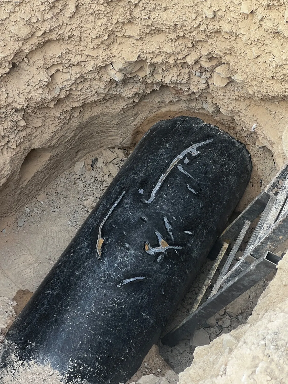
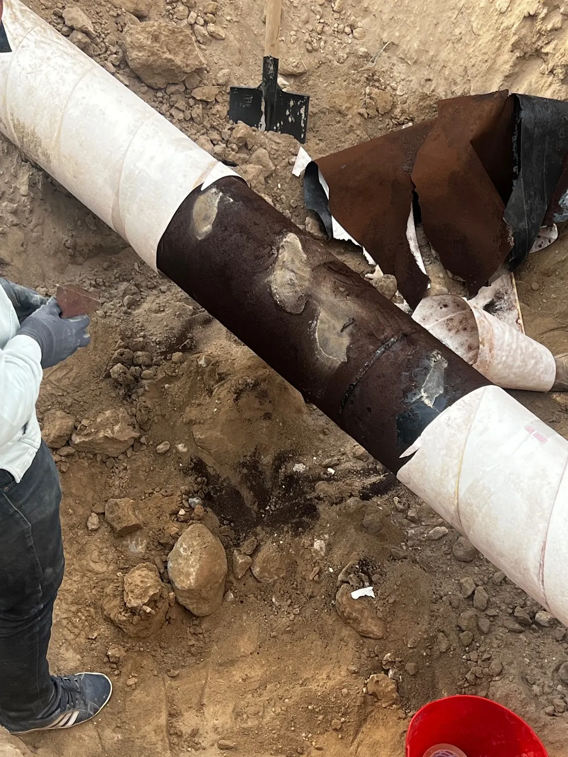
Excavate high-priority defect areas based on size and severity. Clean the pipe for visual inspection, and perform NDT, such as thickness gauging, if corrosion is observed. Soil testing may include chemistry, resistivity, pH, and sulfate-reducing bacteria (SRB). Key tests include:
Prioritize repairs based on coating condition, pipe wall thickness, and CP performance. Validate the indirect inspection methods, recommend repeat inspections or method changes where needed, and define the next assessment date, periodic inspection intervals, and corrosion control actions.
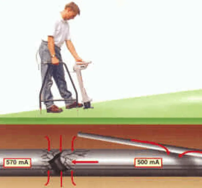
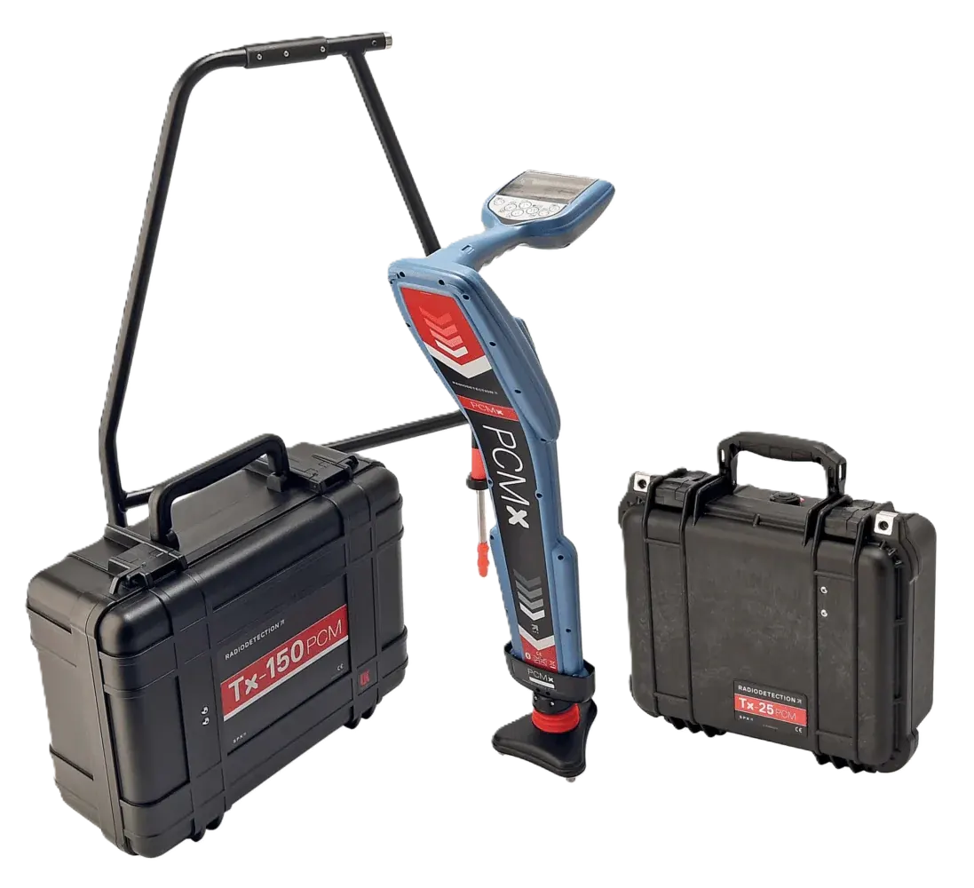
PCM is an indirect coating inspection method used for CP troubleshooting and coating fault detection. A transmitter injects signals at selected frequencies, and the receiver measures current to identify large defects, burial depth, and pipeline route. It is useful in inaccessible areas such as roads, high-resistivity soils, and river crossings.
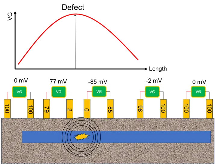
ACVG complements PCM and can detect small coating defects with sub-meter location accuracy, reducing unnecessary excavation. It measures the voltage gradient over coating faults using AC current. It is especially effective with PCM in high-resistivity areas or locations where the signal drops. Current is injected, readings are logged at short intervals, and plotted changes are used to locate defects.
With a fixed current, a drop in coating resistance changes the voltage according to Ohm's law. This voltage change creates a gradient between the A-frame probes. During the survey, voltage gradient is recorded against distance, and spikes in the plot indicate coating defects.
DCVG detects coating defects by measuring the voltage gradient between two reference electrodes. The gradient magnitude helps estimate defect severity.
CIPS is fundamental for evaluating CP performance, interference, coating quality, and minor defects, especially when paired with DCVG. According to NACE TM0109 and SP0502, close-interval pipe-to-reference potentials are measured with a data logger at short spacing along the pipeline. All current sources are interrupted synchronously. Instant-off potentials verify protection criteria, while comparison of on/off readings helps identify coating faults. The method requires an operating CP system, a polarized line, and electrical access through test points. If test points are not available, temporary access points may be installed.